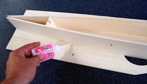
1) Glue outriggers 7 to main floor panel 6 on a flat surface.
The rear edges should be completely flush with each other. Chamfer the rear inner edges of fuselage sides 8 so that they will
meet squarely with fin support 13 when pulled together.
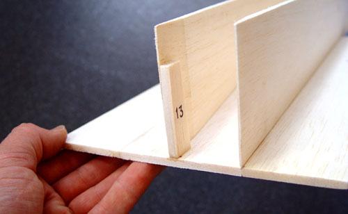
3) Pull fuselage sides together onto fin support
13 ensuring that it is ABSOLUTELY CENTRAL within floor 6, and at 90 degrees vertical to it. The fuselage sides must also be
level with floor 6 before glueing! Note that when pulled onto 13 the fuselage sides will no longer be at the absolute rear
of 13, this is normal.
5) Glue fin centraliser 12 in place 160mm from the rear,
making sure that it is flush with the upper edges of 8s (the gap beneath 12 is necessary for battery pack clearance on tractor
versions). Then run thin cyano along the un-glued portion of fuselage sides i.e. from the handgrip cutouts to the back of
the assembly.
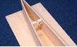
7) BEFORE adding sidepods 14, glue
3/16" square stock along the slot where shown to make up the tailplane support
rails, leaving a 30mm gap in the bottom rails 60mm from the rear where the elevator servos will be fitted later. Mark this
gap on the outside of 14s to help you cut the servo apertures later, or they can be cut out now if desired.
9) Add sidepods 14 to the OUTER edge of outrigger
7. At this stage a pair of 50mm pieces of scrap 3/16" sheet should be glued in place where shown to steady the front of the
sidepods 14 while working on the rear end of the model.
|
 |
|
|
|
|
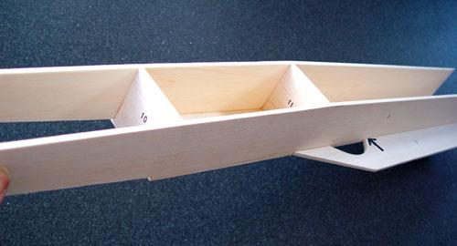
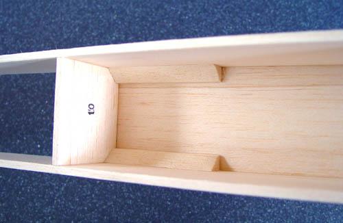
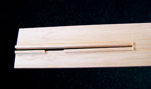
2) Ensure that fuselage sides are flush with the back, and
glue them along the INNER edges of 6 but ONLY apply glue from the front as far back as the rearmost extent of the handgrip
cut-outs (arrowed). Use formers 10 & 11 for alignment and when happy glue them in place. Former 10 is positioned on top
of floor 6 at its front extent, and former 11 goes 205mm behind former 10. NOTE: The gradual taper on fuselage sides
8 goes to the TOP FRONT.
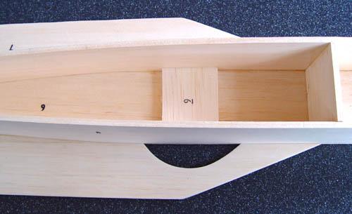
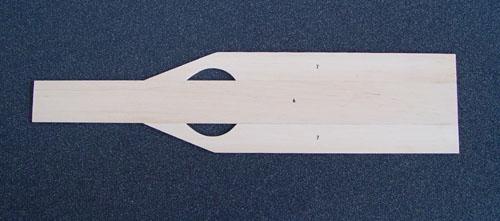
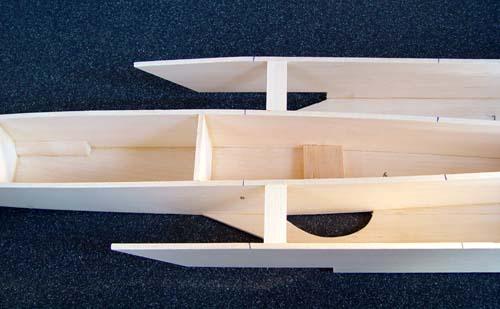
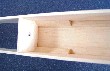
4) Glue handgrip reinforcement piece 9 in
place on floor 6 so that it is exactly between the cutouts in outriggers 7.
6) From the flat-edged triangle stock, cut
two 2¾" pieces and glue them along the bottom fuselage corners immediately behind former 10.
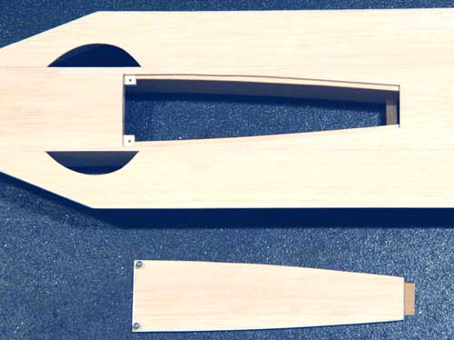
8) Also cut out the radio access hatch which
originates immediately behind handgrip reinforcement piece 9. On pusher versions this is 150mm long; on tractor versions it
needs to be 250mm long (shown here). It is secured using the ply tongue at the rear, and the two hatch securing blocks and
screws at the front. The edges of the hatch are supported using pieces of 3/16" square stock along the inner edges of fuselage
sides 8.
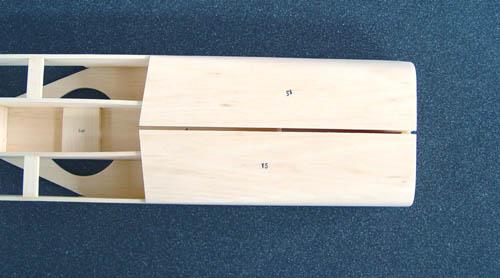
10) Glue the 4 long triangle pieces per side
to the top edge of 14s and bottom corner between 14s and 7s and add both rear upper decks 15 leaving a 3/16" gap for the fin,
and making sure that their rear edges are exactly flush at the back end. THIS IS IMPORTANT as the front edges of 15s
determine the wing position. The four rear corners can now be rounded off, but be careful not to exert too much pressure on
the structure which can break part 12! Fitting the 90mm spacer of 3/16" square stock at the FRONT of this gap will help here.
|
|
|
|
|